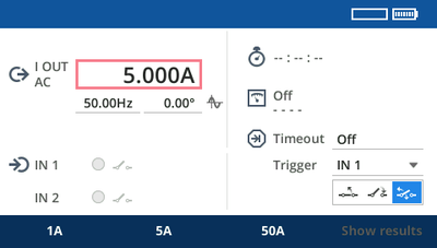
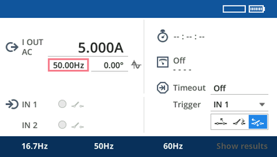
I OUT - AC (110 A) and DC (100 A) current output: see Configuring I OUT.
The sockets of I OUT allow connecting high-current plugs as well as regular 4 mm/0.16 " banana plugs.
WARNING
Death or severe injury caused by high voltage possible Inductive loads may contain a lethal amount of energy if charged with current. The amount of energy depends on the size of the inductive load, the strength of the applied current, and the frequency. To give an example, 350 mJ are assumed as safe according to the safety standard IEC 61010-1. Particularly critical devices are potential transformers or current transformers, but also the inductive part of other test objects can be critical.
If you connect loads >0.3 mH to the COMPANO 100 current output I OUT, do not touch the outputs or anything that is connected to them.
V OUT - AC (150 V) and DC (220 V) voltage output: see Configuring V OUT.
IN 1 and IN 2 can be configured to be either:
binary inputs to connect dry (potential-free) or wet contacts (carrying potential when closed),
or analog voltage or current inputs. By means of a current clamp or a shunt, you can use IN 1 and IN 2 to measure current (see Configuring IN 1/IN 2).
WARNING
Death or severe injury caused by high voltage possible The binary and/or analog inputs IN 1 and IN 2 may conduct hazardous voltages. The insulation against other potential hazardous voltages is implemented as functional insulation, and they are not isolated against each other (common N).
Never connect touchable test objects to the inputs without having secured the danger zone.
Death or severe injury caused by high voltage possible Although the output voltages of the current generators are within touch-safe limits, the insulation to other input and output groups is implemented as basic insulation only. Therefore, the outputs can conduct life-threatening voltages in case of a single failure.
If it is not possible to use the safety test leads and safety sockets, observe the wiring instructions and safety precautions given in chapter Wiring and Safe Connection.
Do not touch the current signals while the COMPANO 100 is powered up.
Each screen that is displayed on the graphical user interface has its "focus" on a particular control element. Text or numbers in entry fields appear black on white background, which indicates that you are in Navigation Mode. Turn the jog dial wheel to move the focus to other control elements of this screen. Once the focus is on the element of your choice, press the wheel.
Depending on the control you have selected, pressing the wheel may lead you to a next level screen, toggle a setting, or enter a field for changing a value or a setting. If you pressed the wheel on an entry field, text or numbers in that entry field appear white on blue background, which indicates that you are in Setting Mode.
The battery status icon indicates the battery's state of charge.
If the icon blinks red, the battery is running low, and an automatic system shutdown will be initiated very soon. To prevent the shutdown, connect the charger.
A flash symbol next to the battery status icon indicates that the battery is charging.
If the flash symbol next to the battery status icon temporarily disappears while charging the battery, you draw more power from the battery than the charger is able to provide in that moment.
Too hot for charging. A thermometer symbol next to the battery status icon indicates that the battery is too hot to be charged. Let the test set and the battery cool down, then try again to charge it.
Too cold for charging. A snow flake symbol next to the battery status icon indicates that the battery is too cold to be charged. Slowly warm up the test set, then try again to charge it.
Thermal image:
The thermal image icon represents a progress bar-like temperature gauge displaying the actual temperature conditions of the COMPANO 100 test set. COMPANO 100 monitors its operational temperature at various places; this temperature gauge reflects the highest temperature value.
Test set temperature OK.
Test set temperature getting critical.
When the temperature limit is reached, that is before an overheating condition causes a damage, the outputs switch off automatically, and the test stops.
Test set temperature too high; current output was ended by the temperature exceeding its limit.
With switched off outputs, the thermal image icon represents an indicator how much the test set has already cooled off.
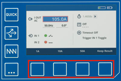
Below the graphical user interface, there are four soft keys.
Their functions vary, depending on the screen and the position of the focus. A key's present function is indicated at the bottom of the screen right above the menu key. In some cases these keys act as acceleration keys to set a specific value, in other cases they provide a certain functionality:
COMPANO 100 comes with a sophisticated keyboard backlighting. The pattern of the backlighting is meant to provide you with status information at one glance.
Backlight color
Meaning
Green
The function is ready to start, or there is a binary contact open. Examples:
Start/Stop key: test set is ready to be started; Start/Stop key was not pressed yet.
Input IN 1 or IN 2 configured to be binary: input is ready but presently the contact connected to it is open.
Timer: Timer is presently running.
Red
Voltage could be present. Examples:
Input IN 1 or IN 2 configured to be analog: currently measuring.
Input IN 1 or IN 2 configured to be binary: binary contact is closed.
I OUT or V OUT: output is active.
Timer: the Timer has stopped.
Red blinking
Alarm. Examples:
Input IN 1 or IN 2 configured to be analog: the measurement is out of range.
I OUT or V OUT: output is overloaded.
Blue
The focus is on this function. There is always only one key blue at a time.
White
The function is configured and ready for operation, but presently not in use. This is, for example, because the function is not activated.
No backlight
The function is not ready for operation. Nevertheless you can press that key; in some cases you might be able to activate the function.