| Other application modules is a group holding various application modules. |
Cable shield current measurement
| WARNING | ||
 | Death or severe injury caused by high voltage possible
Inductive loads may contain a lethal amount of energy if charged with current. The amount of energy depends on the size of the inductive load, the strength of the applied current, and the frequency. To give an example, 350 mJ are assumed as safe according to the safety standard IEC 61010-1. Particularly critical devices are potential transformers or current transformers, but also the inductive part of other test objects can be critical.
|
Use the Micro-ohm application module to measure a device under test, for example, a shunt or a closed circuit-breaker, or to verify the integrity of a grounding system by carrying out a ground grid continuity measurement. The ground grid continuity measurement involves measuring the point-to-point resistances within a ground grid. This is to ensure that all parts of the grounding system, e.g. raisers, are properly interconnected with one another. That way, this method detects improper construction work and deterioration.
Refer to Micro-Ohm application module for accuracy specifications, cable length, and the supported maximum resistance of the device under test.
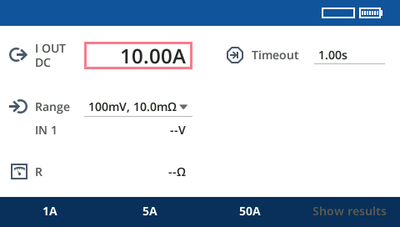
Use the jog dial wheel to set a current value of your choice at I OUT.
Set the Timeout. 1 second is a good default value to start with.
To disable the timeout, set it to Off.
Set a proper measurement range depending on the expected result. If in doubt, use the smallest range; the test set will notify you if the measurement range should not be sufficient.
Press the Start/Stop key to start the current output.
It takes a short moment (around 500 ms) for the result to become stable. Then you will get to see the current that COMPANO 100 injected into the device under test, the measured voltage at IN 1, and the resistance value at R.
The measurement stops automatically after the configured Timeout. Press the Start/Stop key to end the measurement manually.
Even if the output switches off due to output current time limitations, the result is still valid.
A typical measurement time of 1 second can prove insufficient if the device under test comprises current transformers, which may be the case in dead tank breakers with bushing current transformers (CTs), or in some cases in GIS stations (gas-insulated substations). In such cases we need currents with a longer "burn-in" time. Currents below 100 A and times above 1 second are recommended.
If in doubt whether the time is sufficient, make measurements with different times. If the results depend significantly on the timeout, the timeout is generally too short. Some CTs may require times up to 60 seconds. In such a case, 10 A is a good test current.
A good substation or transmission tower grounding system is crucial to protect people from injury and equipment from damage. International standards such as EN 50522:2022, IEEE Std 80-2013 or IEEE Std 81-2012 give guidelines on how to measure the impedances of such grounding systems.
The Ground impedance application module can test smaller grounding systems with a diameter of up to 30 m/100 ft using an auxiliary current probe. With the accessory CIB1 the test current can also be injected using a de-energized medium voltage cable or overhead line of up to 10 km/6 miles. Some test setups may also require a CP GB1 for safety reasons, see CIB1 User Manual for details. Note: no other grounding system must be nearby.
The fall-of-potential method, as it is called in the EN 50522 or IEEE standards, is a good solution for measuring the ground impedance of a substation. The current is fed into a remote ground via a long cable. This remote ground can be any ground from a simple grounding rod to another large grounding system. Usually a grounding rod, referred to as auxiliary current probe, is used. With a CIB1, the grounding system of a remote sub-station can be used to inject the test current via a de-energized power cable.
The distance between this probe and the grounding system under test should be five to ten times the diameter of the grounding system. A larger distance will provide more accurate results. In general, the setup must represent worst case conditions that may occur during a single-line fault. This must be clarified for each grounding system individually.
Then measure the voltages with a second test probe at various distances around the grounding system under test. If possible, choose the measurement points in a 90 º angle (bird’s-eye view) relative to the current path.
The measured data at a large distance away from the grounding grid (typically three times the length of the grounding grid or, for example, 62 % of the injection distance) allow the calculation of the overall ground impedance.
| Distance | EN 50522:2022 | IEEE 81 |
| Auxiliary current probe distance (injection) | ≥ 8 times the maximum diameter of the grounding system under test but not less than 40 m (130 ft) | ≥ 5 times the maximum diameter of the grounding system under test |
| Potential probe distance (measurement) | ≥ 5 times the diameter of the grounding system in measurement direction but not less than 20 m (65 ft) | E.g. 62 % of the distance used for injection |
We recommend to measure at different distances. If the distance is high enough, the measurement points should all show similar results. If the points are set too close to the grounding system under test, close to other grounding systems, or over buried pipes, the obtained results are not stable.
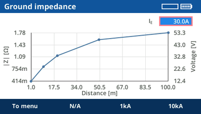
The example below shows the plot of the resistance in different distances from the grounding grid under test. The ground impedance to distant earth will be about 280 mΩ. By choosing a 90 ° angle for the measurement, there is no risk to get into the influence zone of the auxiliary current probe (marked red below).
The ground impedance test incorporates a guided workflow consisting of four steps that can be executed one after another.
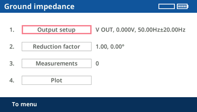
It is always possible to return to the menu or to go back to a previous step. For example, it is possible to plot measurements, then go back to the menu and add additional measurements to the previous ones.
Use the Output setup feature to find the best output and setting for the measurement. Depending on the impedance of the auxiliary current probe, the best output can be either V OUT or I OUT. If the other output is expected to provide better results, advice is given during the output setup. If using a CIB1 to inject the test current via a de-energized cable and the ground grid of a remote substation, use I OUT at the CIB1.
| WARNING | ||
| Death or severe injury caused by high voltage or current possible.
Employ the proper test set.
|
|
| *) Warning flag for auxiliary current probes provided by OMICRON. |
| CAUTION | ||
| Minor or moderate injury caused by tripping over the measurement cable possible.
|
Turn the jog dial wheel until the focus is on Output setup. Then press the jog dial wheel once.
The COMPANO 100 test set's V OUT is configured as output by default.
Connect the ground of the grounding system under test to the black socket of V OUT using a measurement cable. Depending of the grounding system, a Kelvin clamp, a Y clamp or Kelvin screws can be the preferred choice.
Depending on the used standard, position the auxiliary current probe at the required distance . If in doubt, choose a 150 m/450 ft distance for grounding systems up to a diameter of 30 m/100 ft.
Connect the auxiliary current probe to the red socket of V OUT using the cable drums and a crocodile clamp.
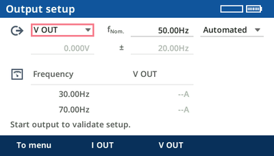
If at Output setup the power line frequency fNom. is set properly, the suggested frequencies should be 20 Hz above and 20 Hz below the power line frequency. The following steps of the guided workflow consist of two points per measurement with frequency-selective filtering to filter out disturbances of the power line frequency. The result is an interpolation of the two measurement points.
Automated output configuration
For most cases, it is sufficient to use the automated mode.
Press the Start/Stop button for COMPANO 100 to search for the optimum output voltage for the current test setup.
In cases, however, where the ground injection point has a particularly low impedance, it could be that, after the automated setup, the lower part of the display suggests I OUT being the better choice for the output. In such a case, simply rewire from V OUT to I OUT, and repeat the automated setup.
Manual output configuration:
In certain cases, it makes sense to apply a manual output setup configuration. To do so, switch to Manual and set the individual parameters manually. The closer you set the ± delta frequency value towards the nominal frequency fNom., the steeper the used filters operate. Consequently, measurements very close to the nominal frequency have a better noise suppression, but they also need a bit longer. The default with ±20 Hz was primarily chosen for compatibility reasons with CPC 100 and HGT1 measurements.
Other frequency values can make sense when the system frequency differs from the power line frequency, for example, in 16.7 Hz or 25 Hz railway systems. In such cases, reducing the ± delta frequency to a minimum value (> 0 Hz) proves advantageous. It is also possible to set the ± delta frequency to 0 Hz in order to perform a measurement at a single frequency. This can be used if, for example, measurements at 128 Hz are required, which is a common measurement frequency for some grounding testers.
In general, we suggest to increase the magnitude as much as possible, whereat V OUT currents slightly above 200 mA are possible. When you are in manual mode, the lower part of the display shows hints helping you to find the best output configuration.
In case the current you selected cannot be reached or an overload occurs, the contact resistance to the soil of the auxiliary current probe might be too high. To keep the resistance to the soil low, position several electrodes in a distance of a few meters from one another, and connect them all together. This also reduces the hazard of high voltages around the electrode.
The point of current injection, which was defined and configured in this step, will not be altered in the subsequent chapters. It stays where it is throughout the whole procedure.
By pressing the To menu soft key you can return to the guided workflow overview. Nevertheless, the configured settings are remembered for the following steps.
Turn the jog dial wheel until the focus is on Split factor. Then press the jog dial wheel once.
Split factors need to be considered on grounding systems if they are connected to other grounding systems, e.g. via overhead wires on transmission towers or via underground cables.
For typical examples of current reduction → Split factor.
The ratio (magnitude and phase angle) between effective local ground current and injected current is called current split factor r:
a current split factor of 1 means there is no current reduction,
a current split factor of 0 means there is full current reduction.
In COMPANO 100, the current split factor can be entered manually when it is known , or it can be measured.
Entering the current split factor manually:
When you know the current split factor, enter its magnitude and phase angle. A current split factor of 1 is common, for example, on a transmission tower with no ground wire or with an insulated one. For a current split factor of 1, generally 0 ° is set.
Measuring the current split factor:
Usually, the current split factor is unknown and needs to be measured.
You typically measure current reduction with a Rogowski coil. In many cases, like at a transmission tower, it is not possible to measure all currents in one step, so you have to carry out more than one measurements. These measurements can be performed one after another. COMPANO 100 will then automatically calculate the resulting overall current split factor r based on magnitudes and phases of all measurements.
It is highly important to carry out the current split factor measurements very thoroughly. Each Rogowski coil has a small arrow imprinted on it. Make sure it points into the right direction. If one single measurement is accidentally done wrong, the result of the entire ground impedance measurement will be wrong.
It is possible to measure the current "above" or "below" the current injection point.
Measuring the current below the injection point:
Measure the current below the injection point when the current flow into soil is expected to be smaller than the current that flows upwards into the ground wire. The reason for this is that Rogowski coils have larger measurement errors than the integrated output current measurement of COMPANO 100. In general, it is therefore preferable to measure the smaller currents with the Rogowski coil to get a more accurate current reduction ratio.
The current direction setting in that case is Ground because you measure the currents into ground.
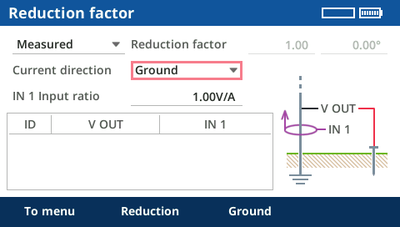
When the current measurement takes place below the source, the Rogowski coils on all legs of the transmission tower must point upwards. They must always point towards the source. It is important to measure on all points where current flows from the injection point to the local grounding system, for example on all legs of a transmission tower.
Measuring the current above the injection point:
Measure the current above the injection point when the current flow into the ground wire is expected to be smaller than the current that flows into the soil via the local grounding system.
The current direction setting in that case is Reduction because you measure the currents that are reducing the effective ground current.
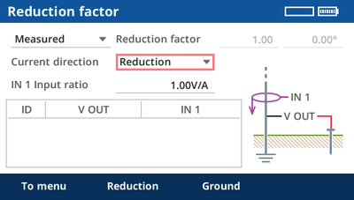
When the current measurement takes place above the source, the Rogowski coils on all legs of the transmission tower must point downwards. They must always point towards the source. It is important to measure on all points where current flows from the injection point to other grounding systems than the local one. For example, measure on all legs of a transmission tower, or on all underground cables that are connecting a distribution substation to other grounding systems.
Performing the measurement:
Configure the measurement range on the Rogowski coil. Use the smallest feasible range to increase measurement accuracy.
Set the IN1 input ratio to the current measurement ratio of the Rogowski coil in the selected range, for example, 100.0 mV/A or 1.0 V/A.
Tips:
If possible, put two or more turns of the Rogowski coil around the leg of the transmission tower. This will increase the measured current and reduce the measurement error. In this case, you will also have to adjust the IN1 input ratio, for example, from 100.0 mV/A to 200.0 mV/A in case of two turns.
Position the Rogowski coil symmetrically around the leg of the transmission tower or the connector of the underground cable.
Do not place the latch of the Rogowski coil directly next to the conductor. The measurement error is higher next to the latch.
You can use the included measurement cables to extend the connection to the Rogowski coil, for example, when measuring distant legs of the transmission tower. In this case, it is recommended to twist the measurement cables to reduce measurement errors caused by inductive coupling.
Install the Rogowski coil, for example, on a leg of the transmission tower or around a low voltage cable in a distribution substation, then connect it to the IN1 input. Verify correct polarity.
Press the Start/Stop button of the COMPANO 100 test set to output the test current and to carry out the measurement.
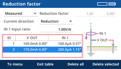
The measurement will be performed with the configured frequencies, and interpolated to the specified nominal frequency. Additionally, the split factor value in the display will be updated.
Check the current shown in the display. It should show approximately the same value as the current displayed during the output setup. If it is significantly lower, the cause may be a loose connection at the cables used for current injection.
Check the voltage shown in the display. It should exceed 1 mV. If it is significantly lower, the cause may be a loose connection at the cables used to connect the potential probe.
Repeat steps 3 and 4, if needed (for example, on all four legs of a transmission tower or on all cable connections to other grounding systems).
All measurements have a unique ID number. If needed, individual measurements can be deleted. To do so, select the measurements using the jog dial wheel, press the wheel, select the measurement to delete, then press Delete selected.
We recommend to thoroughly document what ID is used for what current path. Add a photograph, if possible, showing the direction arrow of the Rogowski coil. For that reason, the IDs are not changed if a result is deleted later.
The current split factor is calculated from the measurements. If it goes beyond 1 or below 0, there is an error in the measurement setup.
Tip: If you doubt that your measurement is correct, you can carry it out with the other current direction, too. If there are major deviations, either an error occurred (for example, wrong direction of the arrow on the Rogowski coil, loose cable contact,...) or the injected current was too small for an accurate measurement result.
By pressing the To menu soft key you can return to the guided workflow overview. Nevertheless, the split factor (entered or measured) is remembered for the following steps.
Measurement setup:
Note: The point of current injection, which was defined and configured in the step Output setup, will not be altered in this chapter. It stays where it is throughout the whole procedure.
| WARNING | ||
| Death or severe injury caused by high voltage or current possible.
In case of a high-current ground fault within the substation or at the transmission tower during the test, high voltages may occur in any wire connected to the grounding grid or leading away from it.
|
Make sure that the auxiliary current probe connected to V OUT is positioned away from the COMPANO 100 test set at least 5 × the diameter of the grounding system of the transmission tower (or the substation). For that purpose, OMICRON provides 150 m of cable.
Connect the black socket of the measurement input IN 1 to the grounding grid under test, e.g. using the same Kelvin clamp, Y clamp or Kelvin screw as for the current injection (→ Output setup).
Position the potential probe into the soil at the required distance from the grounding system, and connect it with a crocodile clamp and the supplied cable drums to the red socket of the measurement input IN 1. If you apply the fall-of-potential method, we recommend an initial distance of 1 m/3 ft.
Turn the jog dial wheel until the focus is on Measurements. Then press the jog dial wheel once.
Enter the measured distance to the grounding system under test into the software, then press the Start/Stop key.
Press the Start/Stop key
After a short time, COMPANO 100 will stop and show a first result.
Now repeat that procedure by positioning the potential probe at several spots with "logarithmically" increasing distances, for example 2 m, 5 m, 10 m, 15 m, 20 m, 30 m, 40 m, 50 m, 70 m, 80 m, 100 m.
We recommend injecting towards line, measuring in a 90 ° angle as shown in the figure above.
If you use another measurement method, for example, the 62 % method mentioned in IEEE Std 80-2013 and IEEE Std 81-2012, refer to the according standard about the current injection and measurement directions.
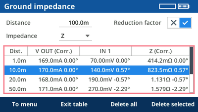
The results can be displayed with or without the current Split factor taken into account.
Current split factor enabled ✓: the results represent the measurement results for the local grounding system.
Current split factor disabled ×: the results represent the measurement results for the total grounding system (for example, including other connected transmission towers).
You can also switch between Z/Phi and R/X representation of the impedance values.
By pressing the To menu soft key you can return to the guided workflow overview. The results are kept.
The plot displays the measured impedances at the various distances and states whether a split factor applies.
You can enter an expected maximum current towards earth in case of a fault. The second axis of the graph displays the expected ground potential raise at the various distances.
The results can be stored on a USB stick.
Excel File Loader
The Ground Impedance EXCEL template, provided with the COMPANO Excel File Loader, can be used to load the measurement, and to generate a report.
After the installation of the COMPANO Excel File Loader go to OMICRON > COMPANO 100 Templates. The default installation path is C:\Program Files\OMICRON\COMPANO 100\Excel Reporting\Templates.
Refer to Excel File Loader for more information.
A step and touch voltage test is carried out to determine
the worst-case touch voltage a person would face when touching a metallic object, for example a fence, in or around a substation in case of a ground fault (current flowing through the person's arm, body and legs towards earth)
the worst-case step voltage a person would face in such a case when doing one step beyond the fence (current flowing into one leg, out the other).
The Step and touch voltage application module of COMPANO 100 acts as a source for the HGT1 accessory from OMICRON.
The HGT1 is an FFT voltmeter, primarily designed for professional acoustical test applications. For step and touch voltage and ground impedance measurements, HGT1 is delivered with an OMICRON software that allows measuring the frequency-selective voltage level by using a real-time Zoom FFT. HGT1 works as an add-on device to COMPANO 100, CPC 100 and CP CU1.
For more information about measuring with HGT1 → Accessory HGT1.
With COMPANO 100, it is possible to measure the step and touch voltages in smaller grounding systems with a diameter of up to 30 m/100 ft.
During a step and touch voltage test, the current is fed into a remote ground via a long cable. This remote ground can be any ground from a simple grounding rod to another large grounding system. Usually a grounding rod, referred as auxiliary current probe, is used. The distance between this probe and the grounding system under test should be at least five times the diameter of the grounding system. A larger distance will provide more accurate results. In general, the setup must represent worst case conditions that may occur during a single-line fault. This must be clarified for each grounding system individually.
The step and touch setup incorporates a guided workflow that consists of three steps, which are executed one after another. The third step generates the desired output signal, only. Do the actual measurement with HGT1.
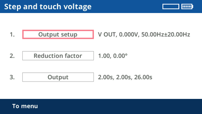
Use the Output setup feature to find the best output and setting for the measurement. Depending on the impedance of the auxiliary current probe, the best output can be either V OUT or I OUT. If the other output is expected to provide better results, advice is given during the output setup.
| WARNING | ||
| Death or severe injury caused by high voltage or current possible.
Employ the proper test set.
|
|
| *) Warning flag for auxiliary current probes provided by OMICRON. |
| CAUTION | ||
| Minor or moderate injury caused by tripping over the measurement cable possible.
|
Turn the jog dial wheel until the focus is on Output setup. Then press the jog dial wheel once.
The COMPANO 100 test set's V OUT is configured as output by default.
Connect the ground of the grounding system under test to the black socket of V OUT using a measurement cable. Depending of the grounding system, a Kelvin clamp, a Y clamp or Kelvin screws can be the preferred choice.
Depending on the used standard, position the auxiliary current probe at the required distance . If in doubt, choose a 150 m/450 ft distance for grounding systems up to a diameter of 30 m/100 ft.
Connect the auxiliary current probe to the red socket of V OUT using the cable drums and a crocodile clamp.
If at Output setup the power line frequency fNom. is set properly, the suggested frequencies should be 20 Hz above and 20 Hz below the power line frequency. The following steps of the guided workflow consist of two points per measurement with frequency-selective filtering to filter out disturbances of the power line frequency. The result is an interpolation of the two measurement points.
Automated output configuration
For most cases, it is sufficient to use the automated mode.
Press the Start/Stop button for COMPANO 100 to search for the optimum output voltage for the current test setup.
In cases, however, where the ground injection point has a particularly low impedance, it could be that, after the automated setup, the lower part of the display suggests I OUT being the better choice for the output. In such a case, simply rewire from V OUT to I OUT, and repeat the automated setup.
Manual output configuration:
In certain cases, it makes sense to apply a manual output setup configuration. To do so, switch to Manual and set the individual parameters manually. The closer you set the ± delta frequency value towards the nominal frequency fNom., the steeper the used filters operate. Consequently, measurements very close to the nominal frequency have a better noise suppression, but they also need a bit longer. The default with ±20 Hz was primarily chosen for compatibility reasons with CPC 100 and HGT1 measurements.
Other frequency values can make sense when the system frequency differs from the power line frequency, for example, in 16.7 Hz or 25 Hz railway systems. In such cases, reducing the ± delta frequency to a minimum value (> 0 Hz) proves advantageous. It is also possible to set the ± delta frequency to 0 Hz in order to perform a measurement at a single frequency. This can be used if, for example, measurements at 128 Hz are required, which is a common measurement frequency for some grounding testers.
In general, we suggest to increase the magnitude as much as possible, whereat V OUT currents slightly above 200 mA are possible. When you are in manual mode, the lower part of the display shows hints helping you to find the best output configuration.
In case the current you selected cannot be reached or an overload occurs, the contact resistance to the soil of the auxiliary current probe might be too high. To keep the resistance to the soil low, position several electrodes in a distance of a few meters from one another, and connect them all together. This also reduces the hazard of high voltages around the electrode.
The point of current injection, which was defined and configured in this step, will not be altered in the subsequent chapters. It stays where it is throughout the whole procedure.
By pressing the To menu soft key you can return to the guided workflow overview. Nevertheless, the configured settings are remembered for the following steps.
Turn the jog dial wheel until the focus is on Split factor. Then press the jog dial wheel once.
Split factors need to be considered on grounding systems if they are connected to other grounding systems, e.g. via overhead wires on transmission towers or via underground cables.
For typical examples of current reduction → Split factor.
The ratio (magnitude and phase angle) between effective local ground current and injected current is called current split factor r:
a current split factor of 1 means there is no current reduction,
a current split factor of 0 means there is full current reduction.
In COMPANO 100, the current split factor can be entered manually when it is known , or it can be measured.
Entering the current split factor manually:
When you know the current split factor, enter its magnitude and phase angle. A current split factor of 1 is common, for example, on a transmission tower with no ground wire or with an insulated one. For a current split factor of 1, generally 0 ° is set.
Measuring the current split factor:
Usually, the current split factor is unknown and needs to be measured.
You typically measure current reduction with a Rogowski coil. In many cases, like at a transmission tower, it is not possible to measure all currents in one step, so you have to carry out more than one measurements. These measurements can be performed one after another. COMPANO 100 will then automatically calculate the resulting overall current split factor r based on magnitudes and phases of all measurements.
It is highly important to carry out the current split factor measurements very thoroughly. Each Rogowski coil has a small arrow imprinted on it. Make sure it points into the right direction. If one single measurement is accidentally done wrong, the result of the entire ground impedance measurement will be wrong.
It is possible to measure the current "above" or "below" the current injection point.
Measuring the current below the injection point:
Measure the current below the injection point when the current flow into soil is expected to be smaller than the current that flows upwards into the ground wire. The reason for this is that Rogowski coils have larger measurement errors than the integrated output current measurement of COMPANO 100. In general, it is therefore preferable to measure the smaller currents with the Rogowski coil to get a more accurate current reduction ratio.
The current direction setting in that case is Ground because you measure the currents into ground.
When the current measurement takes place below the source, the Rogowski coils on all legs of the transmission tower must point upwards. They must always point towards the source. It is important to measure on all points where current flows from the injection point to the local grounding system, for example on all legs of a transmission tower.
Measuring the current above the injection point:
Measure the current above the injection point when the current flow into the ground wire is expected to be smaller than the current that flows into the soil via the local grounding system.
The current direction setting in that case is Reduction because you measure the currents that are reducing the effective ground current.
When the current measurement takes place above the source, the Rogowski coils on all legs of the transmission tower must point downwards. They must always point towards the source. It is important to measure on all points where current flows from the injection point to other grounding systems than the local one. For example, measure on all legs of a transmission tower, or on all underground cables that are connecting a distribution substation to other grounding systems.
Performing the measurement:
Configure the measurement range on the Rogowski coil. Use the smallest feasible range to increase measurement accuracy.
Set the IN1 input ratio to the current measurement ratio of the Rogowski coil in the selected range, for example, 100.0 mV/A or 1.0 V/A.
Tips:
If possible, put two or more turns of the Rogowski coil around the leg of the transmission tower. This will increase the measured current and reduce the measurement error. In this case, you will also have to adjust the IN1 input ratio, for example, from 100.0 mV/A to 200.0 mV/A in case of two turns.
Position the Rogowski coil symmetrically around the leg of the transmission tower or the connector of the underground cable.
Do not place the latch of the Rogowski coil directly next to the conductor. The measurement error is higher next to the latch.
You can use the included measurement cables to extend the connection to the Rogowski coil, for example, when measuring distant legs of the transmission tower. In this case, it is recommended to twist the measurement cables to reduce measurement errors caused by inductive coupling.
Install the Rogowski coil, for example, on a leg of the transmission tower or around a low voltage cable in a distribution substation, then connect it to the IN1 input. Verify correct polarity.
Press the Start/Stop button of the COMPANO 100 test set to output the test current and to carry out the measurement.
The measurement will be performed with the configured frequencies, and interpolated to the specified nominal frequency. Additionally, the split factor value in the display will be updated.
Repeat steps 3 and 4, if needed (for example, on all four legs of a transmission tower or on all cable connections to other grounding systems).
All measurements have a unique ID number. If needed, individual measurements can be deleted. To do so, select the measurements using the jog dial wheel, press the wheel, select the measurement to delete, then press Delete selected.
We recommend to thoroughly document what ID is used for what current path. Add a photograph, if possible, showing the direction arrow of the Rogowski coil. For that reason, the IDs are not changed if a result is deleted later.
The current split factor is calculated from the measurements. If it goes beyond 1 or below 0, there is an error in the measurement setup.
Tip: If you doubt that your measurement is correct, you can carry it out with the other current direction, too. If there are major deviations, either an error occurred (for example, wrong direction of the arrow on the Rogowski coil, loose cable contact,...) or the injected current was too small for an accurate measurement result.
By pressing the To menu soft key you can return to the guided workflow overview. Nevertheless, the split factor (entered or measured) is remembered for the following steps.
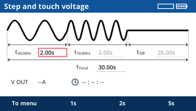
Turn the jog dial wheel until the focus is on Output. Then press the jog dial wheel once.
You can vary the on, off and pause time to meet your needs. Press the Start/Stop key to start the output sequence. That sequence is repeated until manually stopped.
The pause time is meant to save battery power on long testing days.
For more information about measuring with HGT1 → Accessory HGT1.
The results can be stored on a USB stick. They contain the used frequencies, the output current, and the split factor.
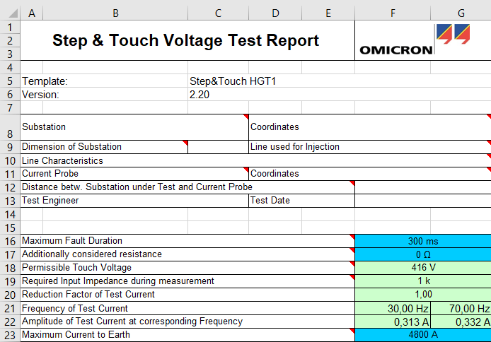
The Step and Touch Voltage EXCEL template, provided with the COMPANO Excel File Loader, can be used to load the data from both the COMPANO 100 test set and the HGT1, and to generate a report.
For more information about the Excel File Loader → Excel File Loader.
For more information about recording and saving step and touch voltage measurements with HGT1, please refer to the HGT1 User Manual.
A soil resistivity test is performed prior to the construction of a grounding system in order to know about the resistivity of the soil in different layers. Its measurement results can be furthermore used in conjunction with grounding grid calculation and simulation software such as CDEGS.
The measurement delivers specific soil resistivity values for different distances between the used current and potential probes that allow drawing conclusions about the layers in the ground in larger depths.
The soil resistivity application module allows performing this test and directly evaluating the results using either the Wenner or Schlumberger method. For example, the Wenner method is shown below
The soil resistivity application module incorporates a guided workflow that consists of two steps, which can be executed one after another.
| WARNING | ||
| Death or severe injury caused by high voltage or current possible.
In the unlikely event of an internal error of the COMPANO 100 test set, higher voltages than expected could occur at output V OUT.
|
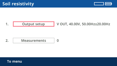
The Output setup is configured to use V OUT with 40 V in the soil resistivity application module. Since for most cases, there is no need to change this configuration, you may skip this step and progress directly to the measurement step.
However, if there are exceptional circumstances, such as a very conductive soil, reduce the voltage as the resulting current might be too high for the voltage output. In such a case, the COMPANO 100 test set would switch off with an error message. If this happens, reduce the voltage, and try again.
Note that for safety reasons this application module is limited to an output voltage of 40 V.
If there are animals close to the measurement location, for example, grazing cattle, it is advisable to reduce the voltage to approx. 10 V.
If the voltage needs to be adjusted, turn the jog dial wheel until the focus is on Output setup. Then press the jog dial wheel once.
A delta frequency value of ±20 Hz from the power line frequency is generally a good choice. If needed, the value can be changed, though. It is also possible to set it to 0 Hz in order to perform a measurement at a single frequency. This can be used, if you, for example, require measurements at 128 Hz, which is a common measurement frequency for some grounding testers.
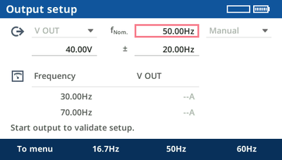
You can test the output configuration by pressing the Start/Stop key.
To get the worst-case value, we recommend starting with the smallest required distance.
During each measurement, the output current is measured. Therefore, there is no need to repeat the output setup, even when replacing the probes.
By pressing the To menu soft key you can return to the guided workflow overview. Nevertheless, the configured settings are remembered for the following step.
The soil resistivity measurement screen displays the wiring setup.
COMPANO 100 supports three different methods for soil resistivity measurements.
Wenner simplified
The Wenner simplified method uses four probes. The two inner probes are potential probes, the two outer probes are current probes. All grounding probes are positioned with identical distance (a) from one another. They are driven into the ground to a depth not more than 1/20th of the distance between the individual grounding probes:
.
The following equation will be used by the device to calculate the soil resistivity ρ: ρ = 2πa|Z|.
Wenner
The Wenner method also uses four probes that are positioned with identical distance (a) from one another. The depth, however, that they are driven into the ground (b), can be specified. The Wenner method is also referred to as equally-spaced agreement.
The following equation will be used by the device to calculate the soil resistivity ρ:
![]()
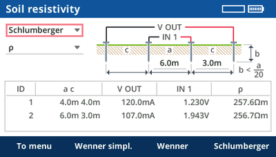
Schlumberger
The Schlumberger method allows two different distances between the grounding probes as shown in the image below (a & c). Therefore, since two grounding probes can be kept where they are, this method requires less rewiring efforts when you do several measurements at different distances.
The Schlumberger method is also referred to as Schlumberger-Palmer agreement or unequally spaced agreement.
The following equation will be used by the device to calculate the soil resistivity ρ:
![]()
| WARNING | ||
| Death or severe injury caused by high voltage or current possible.
In the unlikely event of an internal error of the COMPANO 100 test set, higher voltages than expected could occur at output V OUT.
|
Performing the measurement:
Select the measurement method of your choice.
Place the grounding probes as shown on the display.
Connect the probes to the V OUT output and the IN 1 input of the COMPANO 100 test set. To do so, use the provided measurement cables and crocodile clamps.
Enter the distances to the table of the Soil resistivity screen.
Press the Start/Stop key on the COMPANO 100 test set to output the test current and to carry out the measurement. The measurement will be performed with the configured frequencies, and interpolated to the specified nominal frequency.
Repeat steps 3 to 5 for all measurement distances.
After the measurement, the result will be shown with a unique ID in the results list. To delete individual or all results, select the list with the jog dial wheel.
The result is shown as specific soil resistivity ρ in Ωm. Alternatively, you can also display them as raw impedance value |Z| in Ω. The raw values |Z| can be used to calculate the soil resistivity manually. This is useful if other methods are used, such as the Pole-Dipole or the Dipole-Dipole method.
Typical resistivity of common soil types:
| Soil type | Soil resistivity |
|---|---|
| Moor, marsh, very moist soil | 1 ... 50 Ωm |
| Loess, clay | 20 ... 100 Ωm |
| Humus, acre | 10 ... 200 Ωm |
| Sandy clay | 50 ... 500 Ωm |
| Stony, grassy soil | 100 ... 300 Ωm |
| Glass sand | 200 ... 3000 Ωm |
| Rock | 300 ... 5000 Ωm |
| Granite, freestone | 1500 ... 10000 Ωm |
Soil resistivity is a major factor for the corrosiveness of soil:
| Corrosiveness of soil | Soil resistivity |
|---|---|
| Severe | < 10 Ωm |
| Corrosive | 10 ... 50 Ωm |
| Moderately corrosive | 50 ... 100 Ωm |
| Slightly corrosive | 100 ... 500 Ωm |
The results can be stored on a USB stick.
The COMPANO Excel File Loader can be used to load the data from the COMPANO 100 test set. Afterwards, the data can be copied, for example, into a grounding system calculation software.
For more information about the Excel File Loader → Excel File Loader.
This application module requires a CIB1 accessory. The Cable Impedance application module is used to measure the line impedance of short medium voltage cables or overhead lines with no parallel systems. The length is limited to 10 km/6 miles by the output power of the COMPANO 100 as well as safety considerations.
General information
Make sure that the line under test is shorter than 10 km/6 miles.
Check if there are parallel systems.
Do not test overhead lines with parallel systems.
Use a CP GB1 for cables with parallel systems.
Use a CP GB1 for overhead lines.
Make sure that the line is de-energized and grounded.
Press the emergency switching off button at the COMPANO 100.
Connect the ground terminals of COMPANO 100 and CIB1 to protective earth.
Use a ground point as close to the test set as possible.
Place the COMPANO 100 at a safe distance from the line under test.
Secure the danger zone against unauthorized access.
| DANGER | ||
 | Death due to electric shock or burns
Extremely high voltage and high energy is present when test setup, line under test, and parallel systems are not switched off and secured correctly.
|
Setup without a CP GB1
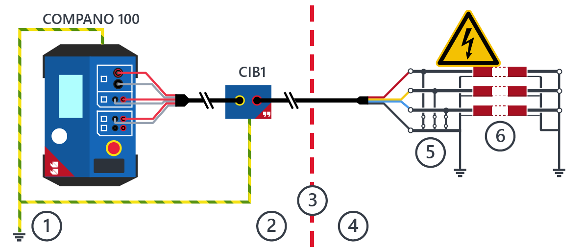
| 1 | Grounding of COMPANO 100 and CIB1 | 4 | Danger zone |
| 2 | Work area | 5 | Local grounding switches |
| 3 | Safety barrier | 6 | Line under test |
| WARNING | ||
| Death due to electric shock
Active or unknown parallel systems can induce dangerous voltages into the line under test. There also is a risk of a lightning strike or fault from an energized parallel system.
|
Setup with a CP GB1
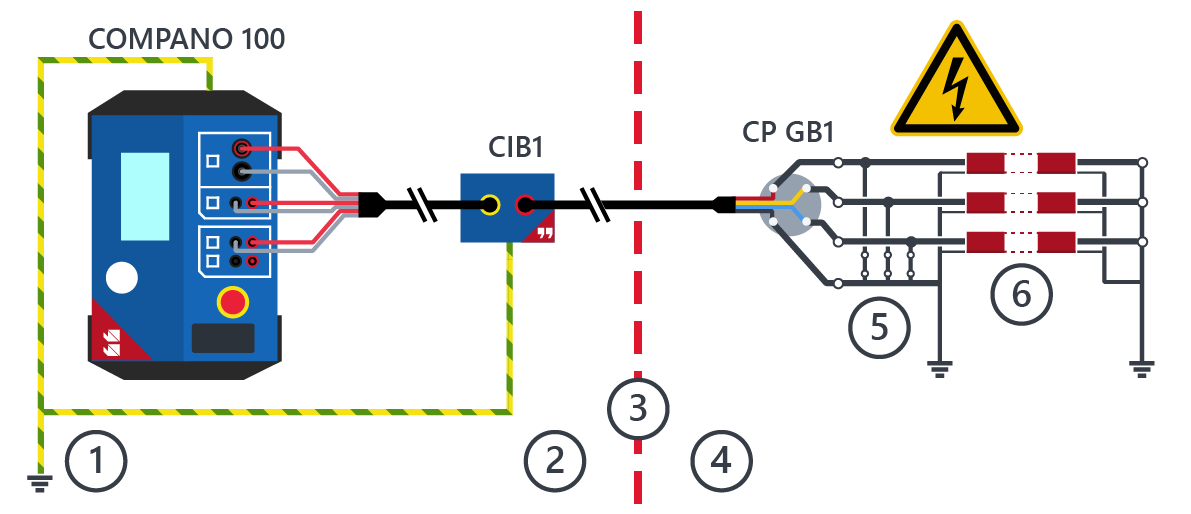
| 1 | Grounding of COMPANO 100 and CIB1 | 4 | Danger zone |
| 2 | Work area | 5 | Local grounding switches |
| 3 | Safety barrier | 6 | Line under test |
| WARNING | ||
| Death due to physical injury
In case of a fault in the system, a high fault current is shorted to ground by the CP GB1. This leads to excessive mechanical movement of the CP GB1 and the grounding lines. The CP GB1 or other mechanical parts can hit persons nearby.
|
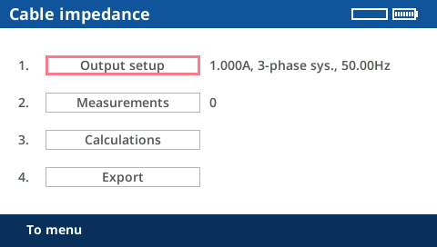
The cable impedance application module uses a guided workflow consisting of the following steps that can be executed one after another.
| WARNING | ||
| Death due to electric shock
There are exposed contacts which could carry high voltage if the working instructions are not followed properly.
|
Before starting an actual measurement, the local grounding of the line under test must be temporarily removed for the measurement.
Do not enter the danger zone if the local end of the line is not grounded.
Keep the time you remove the grounding for the test as short as possible: Only remove the grounding of the local end of the line directly before the test and ground it again directly after the measurement.
The Output setup specifies the line under test and the test method.
Connect the line under test to the COMPANO 100, using a CIB1.
Use the Output setup to specify the setting for the measurement.
The default parameters work for most applications.
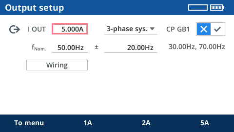
If necessary, change the following parameters:
I OUT - test current for the impedance measurement
Default value: 1.0 A
This value usually does not have to be changed and provides accurate measurement results.
1-phase sys. or 3-phase sys.
Default: 3-phase system
Select 1-phase sys. for single core cables and 3-phase sys. for a 3-phase cable system.
CP GB1 - indicates if a CP GB1 surge arrestor box is used during the test
Default: Off
A CP GB1 is required when testing on overhead lines, mixed lines, or when testing cables with active parallel systems.
fNom.
Default: the nominal frequency specified in Setup > Regional
Select the nominal frequency of the system. The measurement will be performed with frequencies below and above this frequency and interpolated for this frequency.
± - delta frequencies for the measurement
Default: 20 Hz
A setting of ± = 20 Hz with fNom. = 50 Hz specifies that the measurements will be performed at 30 Hz and 70 Hz.
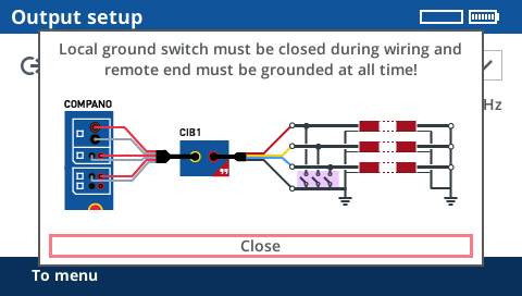
| WARNING | ||
| Death due to electric shock
During the test, the local grounding is removed. A dangerous voltage is present at the contact point. This can lead to an electric shock or large scale skin burns.
|
To display the wiring diagram of the test, press the Wiring button.
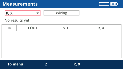
The measurement screen is used to perform the actual measurement.
Open the local ground switch.
Press the Start/Stop key to start the measurement.
Wait for the measurement to finish. It will run through the following steps:
Measuring open-loop voltages
Injecting test-current and measuring the loop-voltage
Calculating the loop-impedance (displayed R, X or Z)
All calculated loop-impedances are displayed on the screen.
Each of the measuring steps is performed for all the required current loops:
L1-E
L2-E
L3-E
L1-L2
L2-L3
L1-L3
L1+L2+L3
If necessary, repeat the measurement by pressing the Start/Stop key again.
Close the local ground switch.
Troubleshooting
| Problem or error message | Possible cause | Measures |
|---|---|---|
| The open-loop voltage is too high to perform a current injection. | The wiring is incorrect. |
|
| The coupling from parallel energized systems is too high. The line under test is too long. |
|
|
| Injection of current not possible (overload). | The impedance of the line under test is too high:
|
|
| Broken fuse |
|
The calculation screen shows the calculated results after a successfully performed measurement.
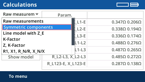
Choose the desired calculation type.
Examples:
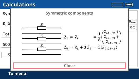
Symmetric components shows the positive sequence and zero sequence results.
After specifying a line length, the results can be shown as an absolute result or relative per km.
Press the button Show model to display the selected model as well as the used equations for the calculation.
The Export screen allows to export all measurement and calculated values after the measurement.
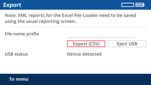
✔ A storage device (USB stick) is plugged into the USB port of the test set.
Add a prefix of up to 8 characters to the file name.
Press the Export (CSV) button.
To remove the storage device from the USB port, press the Eject USB button.
For more information about supported USB storage devices and file systems, → Communication Ports.
The following line models are calculated on the device and displayed directly. Data can be exported as a CSV file or saved for the Excel File Loader.
| Name | Model | Name in CSV or Excel |
|---|---|---|
| Raw measurements | 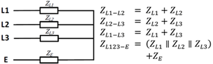 | ZL1-E = L1-E ZL2-E = L2-E ZL3-E = L3-E ZL1-L2 = L1-L2 ZL2-L3 = L2-L3 ZL3-L1 = L3-L1 ZL123-E = L1L2L3-E-AVG |
| Line model with ZE | 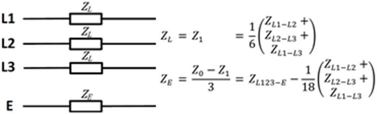 | ZL = Z_L ZE = Z_E |
| Symmetric components | 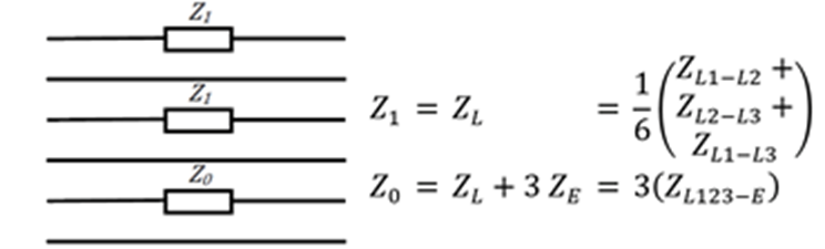 | Z1 = Z_1 Z0 = Z_0 |
| K-factor generic | 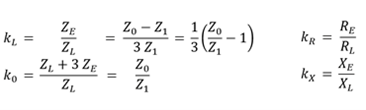 | kL = k_L k0 = k_0 kR = R_E/R_L kX = X_E/X_L |
| K-factor with Z | 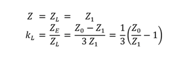 | ZL = Z_L kL = k_L |
| K-factor with RN/ NX | 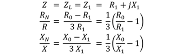 | ZL = Z_L RN/R = R_N/R XN/X = X_N/X |
| Physical model (unsym.) | 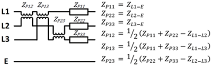 | ZP11 = Z_P11 ZP22 = Z_P22 ZP33 = Z_P33 ZP12 = Z_P12 ZP13 = Z_P13 ZP23 = Z_P23 |
| Physical model (sym.) | 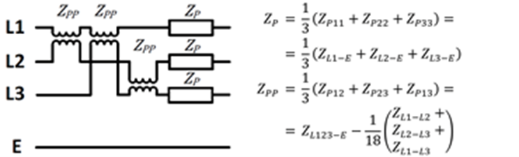 | ZP = Z_P ZPP = Z_PP |
The Cable shield current application module is used to measure the currents on the cable shields of short low and medium voltage single-core cable systems, consisting of one or more parallel systems. This allows to detect unbalanced current distribution and potential overloading of cable shields. The length is limited to 10 km/6 miles by the output power of the COMPANO 100 as well as safety considerations. This application module requires a CIB1 accessory as well a suitable current clamp, → Accessories.
General information
Make sure that the line under test is shorter than 10 km/6 miles.
Check if there are parallel systems.
Use a CP GB1 for cables with parallel systems.
Make sure that the line is de-energized and grounded.
Press the emergency switching off button at the COMPANO 100.
Connect the ground terminals of COMPANO 100 and CIB1 to protective earth.
Use a ground point as close to the test set as possible.
Place the COMPANO 100 at a safe distance from the line under test.
Secure the danger zone against unauthorized access.
| DANGER | ||
| Death due to electric shock or burns
Extremely high voltage and high energy is present when test setup, line under test, and parallel systems are not switched off and secured correctly.
|
Setup without a CP GB1
| 1 | Grounding of COMPANO 100 and CIB1 | 4 | Danger zone |
| 2 | Work area | 5 | Local grounding switches |
| 3 | Safety barrier | 6 | Line under test |
| WARNING | ||
| Death due to electric shock
Active or unknown parallel systems can induce dangerous voltages into the line under test. There also is a risk of a lightning strike or fault from an energized parallel system.
|
Setup with a CP GB1
| 1 | Grounding of COMPANO 100 and CIB1 | 4 | Danger zone |
| 2 | Work area | 5 | Local grounding switches |
| 3 | Safety barrier | 6 | Line under test |
| WARNING | ||
| Death due to physical injury
In case of a fault in the system, a high fault current is shorted to ground by the CP GB1. This leads to excessive mechanical movement of the CP GB1 and the grounding lines. The CP GB1 or other mechanical parts can hit persons nearby.
|
The cable shield current application module uses a guided workflow consisting of the following steps that can be executed one after another.
| WARNING | ||
| Death due to electric shock
There are exposed contacts which could carry high voltage if the working instructions are not followed properly.
|
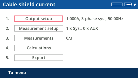
Connect the line under test to the COMPANO 100, using a CIB1.
Use the Output setup to specify the setting for the measurement.
The default parameters work for most applications.
If necessary, change the following parameters:
I OUT - test current for the impedance measurement
Default value: 1.0 A
This value usually does not have to be changed and provides accurate measurement results.
1-phase sys. or 3-phase sys.
Default: 3-phase system
Select 1-phase sys. for single core cables and 3-phase sys. for a 3-phase cable system.
CP GB1 - indicates if a CP GB1 surge arrestor box is used during the test
Default: Off
A CP GB1 is required when testing on overhead lines, mixed lines, or when testing cables with active parallel systems.
fNom.
Default: the nominal frequency specified in Setup > Regional
Select the nominal frequency of the system. The measurement will be performed with frequencies below and above this frequency and interpolated for this frequency.
± - delta frequencies for the measurement
Default: 20 Hz
A setting of ± = 20 Hz with fNom. = 50 Hz specifies that the measurements will be performed at 30 Hz and 70 Hz.
| WARNING | ||
| Death due to electric shock
During the test, the local grounding is removed. A dangerous voltage is present at the contact point. This can lead to an electric shock or large scale skin burns.
|
To display the wiring diagram of the test, press the Wiring button.
This module allows to measure the shield currents on up to 9 parallel single-core cable systems as well as up to 9 auxiliary ground connectors.
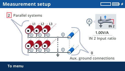
| Parallel systems | Specifies the number of parallel cable systems.
|
| Aux. ground connections | Specifies the number of auxiliary ground connections like copper earth conductors used in parallel to the cable system. The application module calculates the current via these connections. |
| IN 2 input ratio | Specifies the ratio of the current clamp for the shield current measurement.
|
Make sure that the selected measurement range of the current clamp is sufficiently large for the total current.
When in doubt, measure the stray currents with a current clamp before performing the actual measurement while the system is grounded at both sides.
The measurement screen is used to perform the actual measurement.
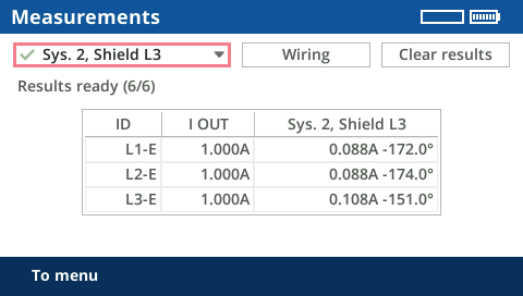
The measurement has to be performed for each cable shield on each parallel system (for example, 12 times in case of 4 parallel systems with 3 cables each) as well as for each auxiliary ground connection.
✔ A current clamp is placed around the selected grounded cable shield or auxiliary ground connection and the provided Coax extension cable is used to connect it to IN2 of the COMPANO 100.
In the selection box, select the cable shield or auxiliary ground connection to be tested.
Make sure that polarity and measurement direction are correct:
Press the Wiring button to display the wiring diagram.
Compare the wiring setup with the measurement direction in the wiring diagram.
Open the local ground switch.
Press the Start/Stop key to start the measurement.
Wait for the measurement to finish. It will run through the following steps:
Measuring open-loop voltages
Injecting test-current and measuring the shield current
All measured raw values are displayed on the screen.
Close the local ground switch.
Repeat the measurement for all cable shields and auxiliary ground connections.
Troubleshooting
| Problem or error message | Possible cause | Measures |
|---|---|---|
| The open-loop voltage is too high to perform a current injection. | The wiring is incorrect. |
|
| The coupling from parallel energized systems is too high. The line under test is too long. |
|
|
| Injection of current not possible (overload). | The impedance of the line under test is too high:
|
|
| Broken fuse |
|
The calculation screen shows the calculated results after a successfully performed measurement.
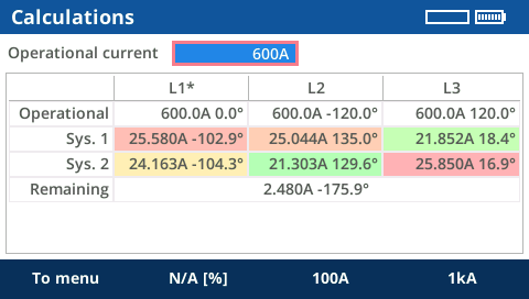
The application calculates and displays the expected shield currents for a symmetric three-phase operational case. The highest values are highlighted red and the lowest values are green. This shows where to expect the highest shield currents. However, this is not an assessment of the shield current.
The results consist of the values for each cable shield on each of the parallel systems as well as the configured auxiliary ground connections.
The remaining current is displayed in the row Remaining. This value usually equals the current via all other ground connections. If there are no other ground connections than the configured auxiliary ground connections, the remaining current should be very close to zero (deviates from zero due to measurement accuracy).
In Operational current, specify an operational current or enter N/A.
The Export screen allows to export all measurement and calculated values after the measurement.
✔ A storage device (USB stick) is plugged into the USB port of the test set.
Add a prefix of up to 8 characters to the file name.
Press the Export (CSV) button.
To remove the storage device from the USB port, press the Eject USB button.
For more information about supported USB storage devices and file systems, → Communication Ports.