Check out the COMPANO 100 Hardware Configuration video on the OMICRON Video Channel (visit https://www.omicronenergy.com/COMPANO100-Hardware).
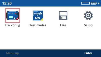
Access all individual hardware configurations from the Home screen by selecting the HW Config icon.
Alternatively, just press the respective key below each input/output.
|
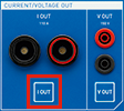
| Press the I OUT key. Whenever you have made a selection, you are automatically forwarded to the next tab presenting you a new selection to pick from. After the last choice, press the respective application module key to continue measuring. |
You have the choice between a 110 A and a 20 A output mode.
Note that the 20 A output limitation provides a slightly more accurate output for small signals than the full-range mode and has a slightly lower compliance voltage. Additionally, the granularity is higher in small current values. In general, in the 20 A mode, currents can be output for a longer period of time. For normal everyday testing, however, this minor accuracy advantage has no big significance.
Note that some application modules overrule the settings of the respective input or output. For example, I OUT is always configured to be a 100 A DC output in Micro-ohm, or always AC in Polarity Check.
|
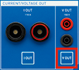
| Press the V OUT key. You have the choice between output modes AC, DC, and AUX DC. Whenever you have made a selection, you are automatically forwarded to the next tab presenting you a new selection to pick from. After the last choice, press the respective application module key to continue measuring. |
In the AUX DC mode, the COMPANO 100 can output a higher current and more power – if required even while no test is running.
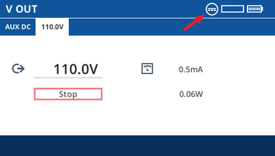
In the AUX DC view you can set the output voltage, and start and stop the AUX DC voltage output.
The measured current and apparent power are displayed on the right side.
As long as the AUX DC mode is active, the corresponding icon ![]() is displayed in the top right corner of every view:
is displayed in the top right corner of every view:
| DANGER | ||
 | Death or severe injury caused by high voltage
When the warning symbol on the COMPANO 100 front panel is lit and/or the AUX DC icon
|
|
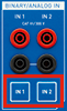
| Press the IN 1 or IN 2 key. Whenever you have made a selection, you are automatically forwarded to the next tab presenting you a new selection to pick from. After the last choice, press the respective application module key to continue measuring. |
IN 1 and IN 2 can be configured to be either:
By means of a current clamp or a shunt, you can use IN 1 and IN 2 to measure current.
If you do not need these inputs, set them to Off. This keeps the user interface clear because functions set to Off are hidden in, for example, QUICK and FLEX.
IN 1/IN 2 binary
| Symbol | Dry | Wet |
|---|---|---|
|
| Connected contact open | Input voltage below configured threshold or connected contact open. |
|
| Connected contact closed | Input voltage above configured threshold. Internally uses a voltage hysteresis to suppress interferences. |
Deglitching input signals:
In order to suppress short spurious pulses, you can configure a deglitching algorithm. The deglitch process results in an additional dead time and introduces a signal delay. In order to be detected as a valid signal level, the level of an input signal must have a constant value at least for the deglitch time.
| Input signal Input signal deglitched |
|
Debouncing input signals:
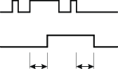
For input signals with a bouncing characteristic, you can configure a debounce function. That means, the first bounce of the input signal causes the debounced signal to be changed, too, and then kept on this value for the duration of the debounce time.
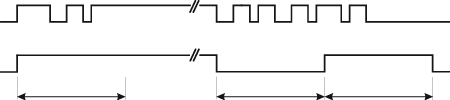
The figure below illustrates the debounce function. At the right-hand side of the figure, the debounce time is set too short. As a result, the debounced signal changes to “high” once again, even while the input signal is still bouncing, and does not drop to low level until the expiry of another Tdebounce period.
| Input signal Input signal debounced |
|
Being an analog input, IN 1/IN 2 measures voltage signals up to 300 V AC or DC. By means of a current clamp or a shunt, you can use IN 1/IN 2 to measure current.
COMPANO 100 only measures voltages on IN 1/IN 2 after you have activated the test set by pressing the Start key. Else no measuring takes place. In case you wish to only measure voltage, disable all outputs. Then activate the test set by pressing the Start key.
|
| The timer can be started and stopped by events you choose. By default, the timer is on. |
Examples of timer start/stop events:
Note: In principle, you can define all kinds of triggers you want, regardless whether or not they are feasible. You can, for example, set a transition from sequence step 5 to sequence step 6 in FLEX as trigger having defined three sequence steps, only. In such a case, the trigger condition is never met.
COMPANO 100 only measures timer start/stop events after you have activated the test set by pressing the Start key. Else no measuring takes place. In case you wish to only measure and test timer start/stop events, disable all outputs. Then activate the test set by pressing the Start key.
When the timer stops, the respective screen shows the result. The timer does not restart in such a case; you need to clear the results beforehand. This is why it makes sense, in particular in FLEX applications, not to define an end condition. The timer does not stop, however, with the sequence changes, intermediate results are recorded anyway.
For phase calculations and certain features, such as the frequency selective measurement (fsel), COMPANO 100 uses an AC reference signal.
This selected reference signal directly affects the measurements done by COMPANO 100 by means of the input signals at IN 1 and IN 2. Should the reference signal be implausible or invalid, all quantities calculated from the reference signal will be wrong. This can happen when, for example, there is nothing connected to the I OUT output or the IN 1/IN 2 inputs but they are set to be a reference signal.
The search for reference signals is done in the below listed order from 1 ... 4. If one of them succeeds to become a reference signal, the rest is ignored.
If I OUT is configured to be an AC output, I OUT is used as reference signal.
Else, if V OUT is configured to be an AC output, V OUT is used as reference signal.
Else, if IN 1 is configured to be an AC input, IN 1 is used as reference signal.
Else, if IN 2 is configured to be an AC input, IN 2 is used as reference signal.
| Define a calculated measurement from a combination of two source quantities, such as output current and an input voltage. Depending on the source 1/source 2 combination, different measurements are possible. For example: from an AC voltage and an AC current you can calculate quantities like Z, P or even Rs and Ls. Other combinations, however, such as a binary input and an DC current, do not allow calculated measurements. |
Resistance R, and either inductance Ls in H (series equivalent circuit), capacity Cp in F (parallel equivalent circuit), or capacity Cs in F (series equivalent circuit) are just another representation of the impedance Z measurement; Z is displayed in its components.
Using Rs and Ls, the impedance is given by: Z = Rs + j ω Ls, where ω = 2 π f, and the frequency of the Reference Signal (→ COMP0075_Reference_signals) is used for the calculation.
Using Rp and Cp, the admittance is given by: 1 / Z = 1 / Rp + j ω Cp, where ω = 2 π f, and the frequency of the Reference Signal (→ COMP0075_Reference_signals) is used for the calculation.
Using Rs and Cs, the impedance is given by: Z = Rs + 1 / (j ω Cs), where ω = 2 π f, and the frequency of the Reference Signal (→ COMP0075_Reference_signals) is used for the calculation.
Cs and tan(δ) is another representation of Rs and Cs with tan(δ) = Rs / |Xc| and Xc = 1 / (j w Cs).
Calculated measurements use frequency-selective settings if the analog input IN 1 is set to "frequency selective measurement" (see IN 1/IN 2 analog ► fsel).
COMPANO 100 only carries out a calculated measurement after you have activated the test set by pressing the Start key. Else no measuring takes place. In case you wish to only measure, disable all outputs. Then activate the test set by pressing the Start key.