| Use FLEX to define and output a sequence of steps. Such a sequence step can be a signal state (a constant current or voltage output, for example), a ramp, or a pulse ramp. Each sequence step has a trailing transition that you can parameterize. |
Contrary to QUICK, in FLEX you define the output parameters prior to the output generation. While the outputs are active, you cannot change the parameters anymore.
Entering parameters:
Example: You have set an I OUT of 9.5 A for sequence step 1. If you now define a timeout of 1 s (60 cycles) for that sequence step, you have defined a start value for your test of 9.5 A at I OUT that after 1 s progresses to the sequence step transition, and from there to sequence step 2.
Sequence step transition
The transition from one sequence step to another can be:
"Step" is a non-configurable transition at the end of a sequence step. Nothing happens in this transition; the sequence step n progresses immediately to the next sequence step n+1.
With such step transitions in between the individual steps you can define a sequence whose steps are either triggered by events such as overloads or binary triggers, or by timeouts.
The transition from sequence step n to the next sequence step n+1 is a ramped signal.
The transition from sequence step n to the next sequence step n+1 is a pulse-ramped signal.
| Tips & Tricks |
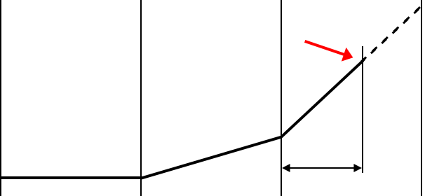
In general, a pulse ramp would be defined as shown in the left part of the picture below.
![]()
Testing, for example, the high setting of an instantaneous trip could take very long that way. There is a quicker way to do this:
Define a state with the pre-fault value and with a timeout as long as needed.
Define a second state with the start value of the pulse ramp (red arrow) and with a timeout of 1 ms, only. This will not considerably affect the first pulse, but it will define the start point.
Then define the pulse ramp with the same reset value like the one that you have set for the pre-fault state.
Setting a reset value other than zero (for example, the nominal value) can be advantageous. In many cases the relay needs that, and COMPANO 100 can output a better signal quality if there is no complete interruption.
The transition from sequence step n to the next sequence step n+1 is a continuous smooth ramp.
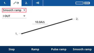
The ramp's start value is the output value defined in this sequence step n.
The ramp's end value is the output value you will specify on the tab of sequence step n+1. When the ramp reaches that value, FLEX progresses to sequence step n+1.
If a trigger is defined in the sequence step n+1, the ramp ends when the trigger condition is met and therefore does not reach its end value.
Specify the slew rate of the ramp. If you want to ramp down, enter a negative value for the slew rate, for example, -1.0 A/s. (Note that the upward ramp illustration will not change.)
| Tips & Tricks |
Usually, smooth ramps are used to test protection functions like df/dt or dI/dt. When the configured slew rate is exceeded, the relay must trip within a certain time.
| Step 1 | Step 2 | Step 3 |
|
|
||
| For example, 50 Hz | For example, 0.9 Hz/s | For example, 1.1 Hz/s |
Example of how this could be tested:
Define a state with the pre-fault value and with a timeout as long as needed.
Define a smooth ramp with a slew rate slightly below the one to test (for example, 0.9 Hz/s if the relay is configured to trip above 1.0 Hz/s).
Define a smooth ramp with a slew rate slightly above the one to test (for example, 1.1 Hz/s).
Configure the timer to start at the state transition to state 3, and to stop on output halt.
Press the Start/Stop key to execute the sequence.
If the sequence stopped in step 2 with a trigger as reason, the relay tripped already below 1.0 Hz/s – there is no timer value available.
If the sequence stopped in step 3 with a trigger as reason, the relay tripped, as intended, above 1.0 Hz/s – the timer shows the trip time.
If the sequence ended without a trigger, the relay did not trip.