Death or severe injury can occur if the appropriate safety instructions are not observed. Unexpected high voltages can occur at output I OUT or V OUT at any time, and the auxiliary current probe carries the full output voltage of the COMPANO 100 test set.
Always press the emergency switching off button before working with these connectors.
Before activating the output, place a guard next to the auxiliary current probe who assures that nobody comes close to it or, even worse, accidentally pulls it out off the ground.
This chapter provides you with examples how to perform grounding system tests.
Death or severe injury can occur if the appropriate safety instructions are not observed. In the unlikely event of an internal error of the COMPANO 100 test set, higher voltages than expected can occur at output I OUT.
Always press the emergency switching off button before working with this connector.
Within the fenced area of a substation there is generally a grounding system with literally hundreds of assets, fence posts, transmission towers and other metallic objects of the substation connected to it. Each one of these objects should have a proper connection that must be verified after erection, during commissioning or changes, or as a later routine test to prove that none of these connections is corroded or otherwise damaged. Should these tests be neglected, a corroded ground connection can result in fatal consequences in case of an earth fault and its fault current not finding a direct way to the station ground.
Ideally, all ground connections are referenced to a single proper ground connection point. The first task is to find such a good ground connection point. In order to do so, randomly pick three ground connection points, for example, grounded metallic structures, and measure them with COMAPNO 100's Micro-ohm application (see image below).
These points should have a certain distance to the COMPANO 100 test set. The grounding packages that OMICRON provides come with 10 m (30 ft) cables. So we recommend a distance of 20 m (60 ft).
A test current of 100 A and a timeout of 1 second in the 100 mV range are generally a good choice.
The grounding packages that OMICRON provides come with three sets of 10 m (30 ft) measurement cables. If testing with a higher current is not possible, try to use two cables set in parallel for the injection (marked with I) and one cable for the measurement (marked with V). This reduces the power dissipated in the cables. If the resistance is still to high, you can use the optional 6 m (19.5 ft) high-current cable set (P0006213) or contact OMICRON Support (→ Support) for a custom cable set.
Do each of the three measurements using four wires, sensing (voltage input IN1) as close as possible to the grounding grid, and the current injection higher on the structure above ground (see image below).
Add together the two acquired results for each structure, for example, for structure 2 the results R12 + R23. Take the structure with the lowest sum as the reference point for the substation.
Of course you can invest more efforts in finding the perfect reference point, but in general any point of a substation that is in sound condition should be suitable to serve as reference point. Using that reference point, all ground connections and grounding points (ground studs) in the vicinity of the reference point are then tested and documented.
Effective testing of the other grounding points should not be done with the sensing wire (voltage input IN1) as close to the grounding grid as possible but rather at the test point itself.
In our example the structure 7 has a grounding stud. That stud must have proper connection to the grounding grid in case it is used to ground a part of the substation to protect the staff. Therefore, connect the measurement reference point directly at the stud, nevertheless keeping current and voltage path separated.
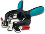
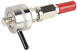
For grounding studs a Kelvin clamp, for threads a Kelvin screw can be a convenient accessory. Both devices clearly separate current and voltage path to guarantee a proper four-wires measurement.
Kelvin clamp
Kelvin screw
In case of a bigger substation, it may become necessary to have more than one reference point. In such cases, the method of finding a good reference point can be repeated. Before starting the second series of measurements, make sure to measure and thoroughly document the resistance between different reference points.
A typical example for current reduction is the grounding system of a high voltage transmission tower. If such a tower has a ground wire, a part of the current that is injected into the grounding system (Itotal) in fact flows through the local grounding system (Ilocal). Another part runs through the ground to other transmission towers (Iremote) and back via the ground wire, therefore reducing the current flow through the local grounding system.
The ratio between the current flowing through the local grounding system (Ilocal) and the total injected current (Itotal) is the current split factor.
A Rogowski coil can be used the measure the current via the legs of the transmission tower. This measurement can be performed with COMPANO 100 leg by leg. COMPANO 100 will then calculate the resulting current split factor. Therefore, it is necessary to specify the position of the Rogowski coil in relation to the injection point (above or below). Refer to Split factor for more details.
Another example would be a pole-mounted distribution substation like shown below. Here, a part of the injected current will flow through the local grounding system (Ilocal). Another part will flow through remote grounding systems, for example of buildings, and through the PEN conductors of low-voltage cables back to the substation.
A Rogowski coil can be used to measure the current flowing through the conductors of the cables. The currents on the phases will cancel themselves, except for the current flowing through the remote grounding system. This measurement can be performed with COMPANO 100 cable for cable. If possible, it is advisable to measure multiple cables at once to reduce the impact of the measurement error of the Rogowski coil. For such an application scenario, the Current direction in the Split factor screen must be set to Reduction. Refer to Split factor for more details.
If the pole-mounted distribution substation has a ground wire on top of the pole, this current must be measured as well since it reduces the current flowing through the local grounding system.